
The Barb Design of Connector Terminals
Terminals are used in connector products as bridges for information and current connection. In order to ensure that the terminal is firmly fixed within the housing part, the terminal’s barb structure and the housing’s interference design are particularly important.
One of the functions of the connector housing is to provide mechanical support, fixing the metal terminals used for connection, which is achieved mainly through terminal barbs and housing interference, making barbs one of the key elements of connector design.
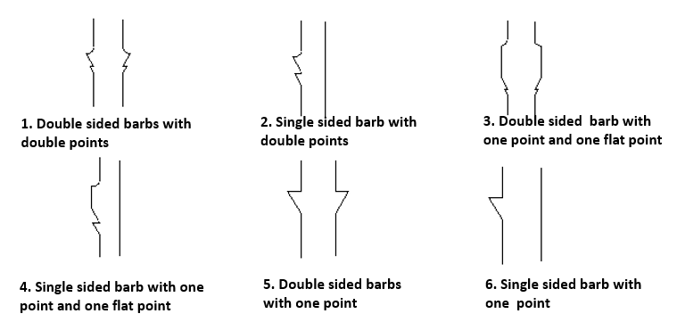 Figure 1: Six common terminal barb structures
Figure 2 shows the interaction between barbs and housing materials under a microscope. When the pin is inserted, the material will be stacked on both sides and in front. When the pin is in place, the extruded material will bounce back, but the plastic housing can not return to the original state after bouncing back, only allowing for partial return to its original state, about 0.04 mm (interference is 0.07 mm). During the withdrawal process, the barb will remove the bouncing material. The material squeezed when the barb is inserted to the end will bounce back when the barb is removed. When the pin is completely removed, the plastic slot fitted with the pin is enlarged for the materials are removed by the barbs. If the terminal is inserted at this time, the retention force of the pin will be greatly reduced. That is why the used plastic housing cannot be reused.
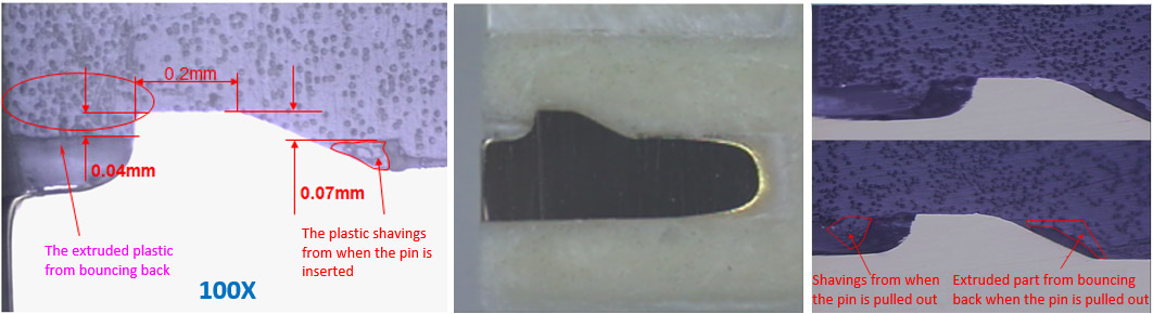 Figure 2: The interaction between barbs and housing materials
Retention force is mainly composed of F1 and F2, which is caused by the exclusion of materials. Therefore, the parameters that affect retention force geometrically are A, B, D, E, F, and G.
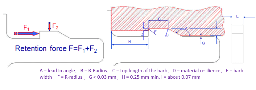 Figure 3: The composition and influence parameters of retaining force
The retention force also has a certain relationship with the interference volume: the larger the interference volume, the greater the retention force. For the same interference height, the interference volume depends on the interference length C. In addition to the influence of parameter C on the retention force, the larger stress area will also cause the increase of the stress distribution area inside the housing and lead to deformation, resulting in cracks in the plastics.
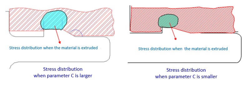 Figure 4: The influence of parameter C on stress distribution inside housing
The problems of barb technology used in connectors with thin plastic bodies are discussed in the following sections. Based on two cases, the contact gap between barb and retaining force/finished product will be discussed. The interference situation was observed by microscope, so as to optimize the main parameters of barb design.
A. The barb structure design problem when assembling the wire and the board, taking FPC connector as an example:
The connector terminal is located outside of the housing groves, which makes the stuffer bump up against the terminal head when being pushed in--making it difficult to be inserted because of the stuffer interference with the rotating contact as it advances. The gap between the front end of the contact barb and the housing pin hole is small so, during the process, the plastic scraps accumulate, making the lower arm of the contact rotate. To improve this problem, Greenconn engineers increased the gap between the front end of the contact and the housing pin hole to accommodate for the plastic chips.
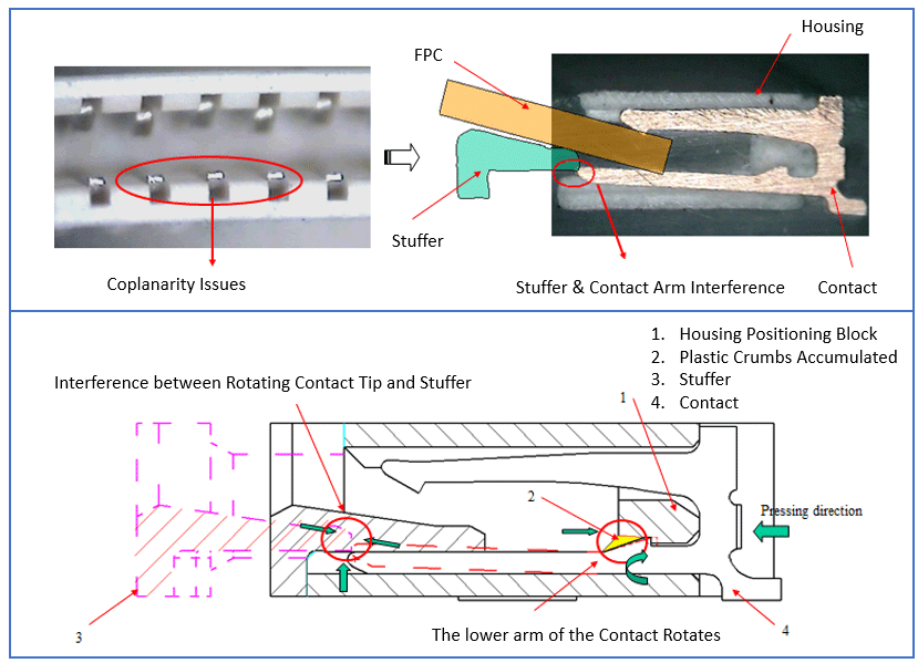 Figure 5: The barb structure design problem of FPC connectors when assembling the wire to the board
B. The barb structure design problem during the connector assembly process: Gap 1 is, on average, 0.12 mm larger than Gap 2. The reason behind this is that the far plastic mouth has a higher amount of contact scraps than the scraps near Gap one, resulting in a slight rotation of the contact (1.02 degrees downward which is about a 0.12 mm gap difference)
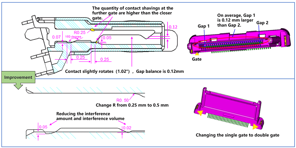 Figure 6: The barb structure design problem and improvement for during the connector assembly process
When the contact is inserted during the connector assembly process, the contact barb will cause damage to the housing surface. The weaker the housing strength is, the more serious the damage is. As a result, there is plastic debris and assembly stress, resulting in the occurrence of the "Furrow phenomenon". Therefore, based on practical problems and the parameters affecting retention force, the following suggestions can be taken into consideration when optimizing the barb structure of terminals. Use the figure below as a reference:
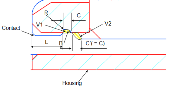 Figure 7: Simple drawing of terminal barb structure
One of the functions of the connector housing is to provide mechanical support, fixing the metal terminals used for connection, which is achieved mainly through terminal barbs and housing interference, making barbs one of the key elements of connector design.
Figure 1: Six common terminal barb structures
Figure 2 shows the interaction between barbs and housing materials under a microscope. When the pin is inserted, the material will be stacked on both sides and in front. When the pin is in place, the extruded material will bounce back, but the plastic housing can not return to the original state after bouncing back, only allowing for partial return to its original state, about 0.04 mm (interference is 0.07 mm). During the withdrawal process, the barb will remove the bouncing material. The material squeezed when the barb is inserted to the end will bounce back when the barb is removed. When the pin is completely removed, the plastic slot fitted with the pin is enlarged for the materials are removed by the barbs. If the terminal is inserted at this time, the retention force of the pin will be greatly reduced. That is why the used plastic housing cannot be reused.
Figure 2: The interaction between barbs and housing materials
Retention force is mainly composed of F1 and F2, which is caused by the exclusion of materials. Therefore, the parameters that affect retention force geometrically are A, B, D, E, F, and G.
Figure 3: The composition and influence parameters of retaining force
The retention force also has a certain relationship with the interference volume: the larger the interference volume, the greater the retention force. For the same interference height, the interference volume depends on the interference length C. In addition to the influence of parameter C on the retention force, the larger stress area will also cause the increase of the stress distribution area inside the housing and lead to deformation, resulting in cracks in the plastics.
Figure 4: The influence of parameter C on stress distribution inside housing
The problems of barb technology used in connectors with thin plastic bodies are discussed in the following sections. Based on two cases, the contact gap between barb and retaining force/finished product will be discussed. The interference situation was observed by microscope, so as to optimize the main parameters of barb design.
A. The barb structure design problem when assembling the wire and the board, taking FPC connector as an example:
The connector terminal is located outside of the housing groves, which makes the stuffer bump up against the terminal head when being pushed in--making it difficult to be inserted because of the stuffer interference with the rotating contact as it advances. The gap between the front end of the contact barb and the housing pin hole is small so, during the process, the plastic scraps accumulate, making the lower arm of the contact rotate. To improve this problem, Greenconn engineers increased the gap between the front end of the contact and the housing pin hole to accommodate for the plastic chips.
Figure 5: The barb structure design problem of FPC connectors when assembling the wire to the board
B. The barb structure design problem during the connector assembly process: Gap 1 is, on average, 0.12 mm larger than Gap 2. The reason behind this is that the far plastic mouth has a higher amount of contact scraps than the scraps near Gap one, resulting in a slight rotation of the contact (1.02 degrees downward which is about a 0.12 mm gap difference)
Figure 6: The barb structure design problem and improvement for during the connector assembly process
When the contact is inserted during the connector assembly process, the contact barb will cause damage to the housing surface. The weaker the housing strength is, the more serious the damage is. As a result, there is plastic debris and assembly stress, resulting in the occurrence of the "Furrow phenomenon". Therefore, based on practical problems and the parameters affecting retention force, the following suggestions can be taken into consideration when optimizing the barb structure of terminals. Use the figure below as a reference:
- B: R-radius should be as large as possible
- V1 must be greater than V2
- R: Should be as small as possible
- L: Length should be at least 0.25 mm
- The strength of housing pin hole and the interference arm of contact barb should be as even as possible.
- Should not have any burrs on the contact barb
Figure 7: Simple drawing of terminal barb structure