Intro to Board to Board Connector Series Part 2
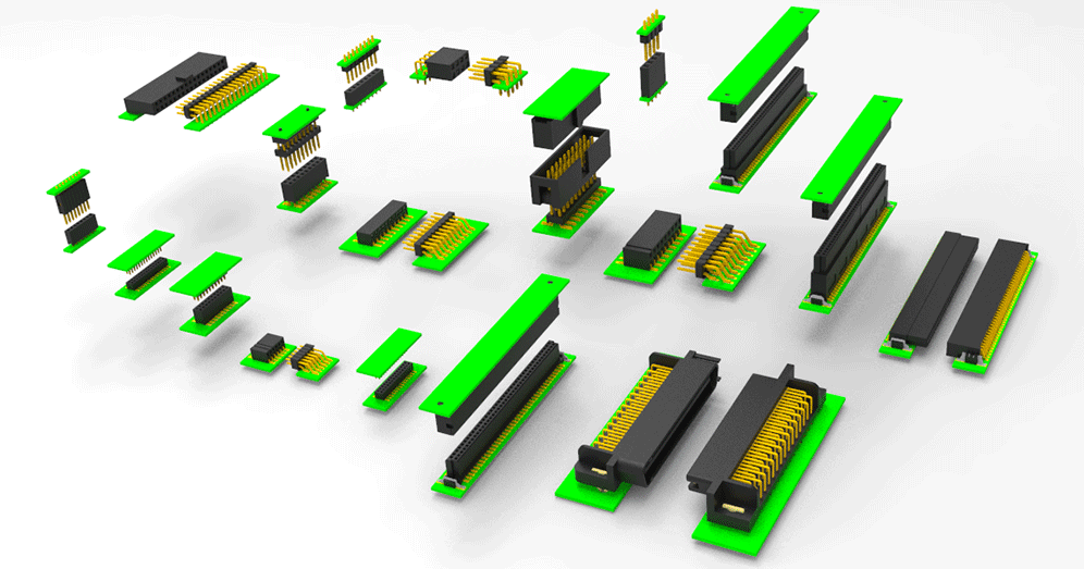
What are the ways to mount BTB Connectors?
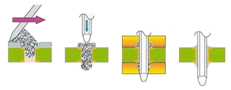
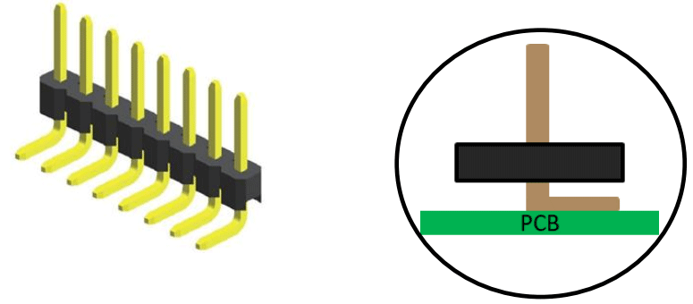
Through-Hole
When a connector is installed on the PCB with its leads inserted into the PCB, it is identified as a through-hole type.
Advantages:
- Through-hole design can create strong bonding at the solder joints, which allows the component to withstand greater environmental stress, such as high accelerations, great collisions, or extreme temperatures. It is commonly used in extreme applications such as military or aerospace.
- Through-hole components can be manually soldered or removed easily, making them cost-effective for prototype developments.
Disadvantages:
- It is expensive and time-consuming to prepare PCBs used for through-hold application as these PCBs must be drilled.
- Through-hole connectors also limit the design freedom with the holes completely drilled through PCBs, which reduces the availability of routing area in circuit design.
There are two options to solder through-hole connectors, Wave soldering and Reflow soldering.
Wave soldering:
Wave soldering is the traditional option used for through-hole components.
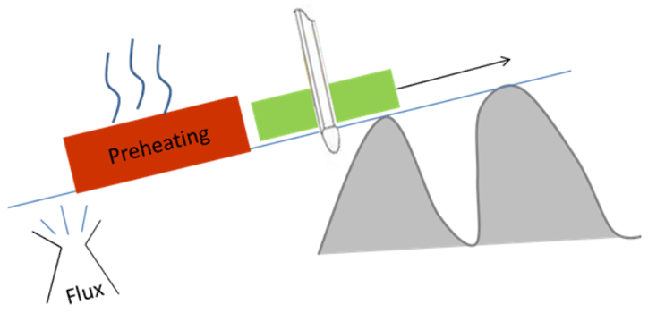
First, components are placed on a PCB on a carrier belt. Then the underside of a PCB is evenly coated with a material known as flux. And after preheating follows fluxing, the belt carries the PCB to soldering. At the soldering zone, there is a pan constantly pumping out liquefied solder. As the PCB sits precisely above the pan and moving through, the solder wets the connectors, bonding to the PCB. Lastly, the PCB moves to the cooling zone to cool down and the wave soldering is completed.
Reflow soldering:
Reflow soldering is the most prevalent soldering method as surface-mounting technology (SMT) dominating over the PCB assembly industry. Through-hole components can also be applied with reflow soldering.
First, the PCB is applied with solder paste and components are placed onto the PCB. Then the PCB enters a pre-heat zone, where the temperature of the board and all the components is slowly raised to right before the melting point of solder. When ready, the PCB then moves into the soldering zone with high temperature, and in a short period of time, the PCB bonds with the components. The surface tension of the molten solder helps keeping the components in place, and if the solder pad geometries are correctly designed, surface tension will automatically align the components onto the pads. Lastly, the PCB moves into the cooling zone and finish the reflow soldering.
Surface Mount (SMT/SMD)
Surface Mount connectors bond their leads to the pads at the surface of a PCB without drilling holes.
Disadvantages:
- Lower cost and time to preparing the PCB since no holes required.
- Solder paste can be precisely applied to better control the soldering.
- More Design flexibility since no drilling holes through the layers.
- SMT can reduce inductance and resistance of component parts
(Which provide Better EMC compatibility and lower radiated emissions due to the smaller radiation loop area and the smaller lead inductance.)
Disadvantages:
- Comparing the through-hole types, surface mount solder joints are weaker against environmental stresses.
- The small lead spaces can make repairment works difficult.
- Surface mount components can only be mounted using reflow soldering
- Due to the heat applied during reflow soldering, surface mount components must use materials meeting the temperature requirement.
Reflow soldering is the only method to effectively attaching surface mount components to printed circuit boards (PCBs)
Additional features to assist mounting BTB connectors:
Weld Tap

Weld tap design is usually coordinated with SMT type connectors to help sharing the stress on the leads to enhance their performance against extreme environmental conditions.
Locating Peg

Locating Peg design is commonly used to assist alignment of connectors to the PCB By making the pegs differently in sizes, or shapes, it can also act as foolproof mechanism to avoid misplacement. Additionally, just like the weld tap design, it can also help share some stresses applied to the leads.
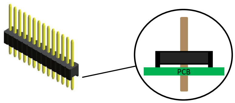
Kinked pins

Kinked pins are used for pre-fastening a through-hole pin header or socket to a PCB. They are particularly useful when in wave soldering process or in using tall components that may cause the connector to move out of position before it can be soldered.

